![G9SX-AD[] BC EX OMRON, elmecon](https://elmecon-mk.com/wp-content/uploads/2024/04/G9SX-AD-BC-EX-OMRON-150x150.jpg)
G9SX-AD[] / BC / EX
17/04/2024
WL-N / WLG
17/04/2024ZE / ZV / ZV2 / XE / XV / XV2
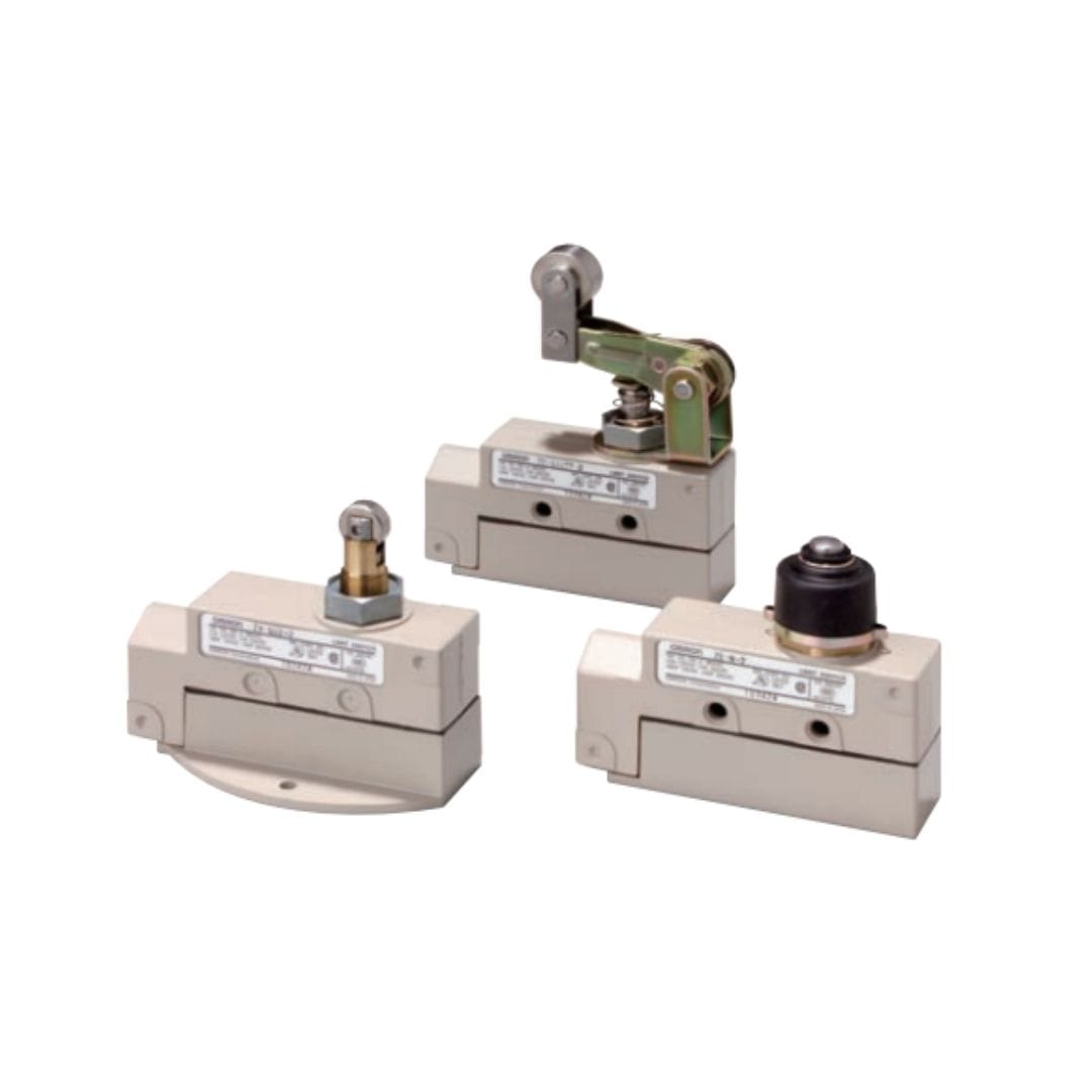
- Z General-purpose Basic Switches are built into ZE, ZV, and ZV2 Switches. They provided high durability and high breaking capacity.
- X Basic Switches with magnetic blowout are built into XE, XV, and XV2 Switches. DC models have also been added to the series.
- Three mounting methods (side, base, and diagonal side) and many types of actuator are available.
- Terminals face the front when the cover is removed for easy connection.
- Switches with ground terminals have CE marking.
- Approved by UL, CSA, and CCC (Chinese standard). (Ask your OMRON representative for information on approved models.)
Download Catalog Click Here!
Category: Switch
Tags: Digital Twin Digitalization distributor PLC omron distributor plc omron di jakarta level swith Machine Vision PLC omron Predictive Maintenance sensor level air Switch Omron timer omron water level control wlc omron
Product Description
Introducing OMRON’s ZE/ZV/ZV2 and XE/XV/XV2 series switches, offering durability and reliability for diverse industrial needs. With multiple mounting methods, various actuators, and front-facing terminals for easy connection, these switches ensure flexibility and convenience. They are CE marked and approved by UL, CSA, and CCC standards, guaranteeing quality and compliance.
Approved Standards
| Agency | Standard | File No. |
|---|---|---|
| UL | UL508 | E76675 |
| CSA | CSA C22.2 No.14 | LR45746 |
| CCC (CQC) | GB/T14048.5 | Contact your OMRON representative for details. |
Note: 1. Models XE, XV, and XV2 are not approved by UL, CSA, and CCC.
2. Ask your OMRON representative for information on approved models.
2. Ask your OMRON representative for information on approved models.
Ratings
| Model | Rated voltage | Non-inductive load (A) | Inductive load (A) | ||||||
|---|---|---|---|---|---|---|---|---|---|
| Resistive load | Lamp load | Inductive load | Motor load | ||||||
| NC | NO | NC | NO | NC | NO | NC | NO | ||
| ZE-[] ZV-[] ZV2-[] |
125 VAC 250 VAC 480 VAC |
15 15 10 |
3 2.5 1.5 |
1.5 1.25 0.75 |
15 15 6 |
5 3 1.5 |
2.5 1.5 0.75 |
||
| 125 VDC 250 VDC |
0.5 0.25 |
0.5 0.25 |
0.05 0.03 |
0.05 0.03 |
|||||
| XE-[] XV-[] XV2-[] |
8 VDC 14 VDC 30 VDC 125 VDC 250 VDC |
10 10 10 10 3 |
3 3 3 3 1.5 |
1.5 1.5 1.5 1.5 0.75 |
10 10 10 7.5 2 |
10 10 10 6 1.5 |
5 5 5 2 2 |
2.5 2.5 2.5 2.5 1.5 |
|
Note: 1. The above figures are for standard currents.
2. Inductive loads have a power factor of 0.4 min. (AC) and a time constant of 7 ms max. (DC).
3. Lamp load has an inrush current of 10 times the steadystate current.
4. Motor load has an inrush current of 6 times the steady-state current.
2. Inductive loads have a power factor of 0.4 min. (AC) and a time constant of 7 ms max. (DC).
3. Lamp load has an inrush current of 10 times the steadystate current.
4. Motor load has an inrush current of 6 times the steady-state current.
| Inrush current | NC | 30 A max. |
|---|---|---|
| NO | 15 A max. |
Approved Standard Ratings
UL/CSA
| Model | Rated voltage | Current | Horsepower |
|---|---|---|---|
| ZE | 125 VAC 250 VAC 480 VAC |
15 A 15 A 15 A |
1/8HP 1/4HP |
| 125 VDC 250 VDC |
0.5 A 0.25 A |
— |
CCC (GB/T14048.5)
| Applicable category and ratings |
|---|
| AC-12 10 A/250 VAC |
Characteristics
| Degree of protection | IP65 (EN60947-5-1)*1 | |
|---|---|---|
| Durability *2 | Mechanical | Z[]: 10,000,000 operations min. X[]: 1,000,000 operations min. |
| Electrical | Z[]: 500,000 operations min., for 15 A, 250 VAC resistive load X[]: 100,000 operations min., for 10 A, 125 VDC resistive load |
|
| Operating speed | Plunger type: 0.01 mm/s to 0.5 m/s Lever type: 0.02 mm/s to 0.5 m/s |
|
| Operating frequency | Mechanical | 120 operations/min |
| Electrical | 20 operations/min | |
| Rated frequency | 50/60 Hz | |
| Insulation resistance | 100 MΩ min. (at 500 VDC) | |
| Contact resistance | 15 mΩ max. (initial value) | |
| Terminal temperature rise | 50°C max. | |
| Dielectric strength | Between terminals of the same polarity |
1,000 VAC, 50/60 Hz for 1 min |
| Between current-carrying metal part and ground |
Z[]: 2,000 VAC, 50/60 Hz for 1 min X[]: 1,500 VAC, 50/60 Hz for 1 min |
|
| Between each terminal and non-current-carrying metal part |
Z[]: 2,000 VAC, 50/60 Hz for 1 min X[]: 1,500 VAC, 50/60 Hz for 1 min |
|
| Vibration resistance | Malfunction | 10 to 55 Hz, 1.5-mm double amplitude *3 |
| Shock resistance *3 |
Destruction | 1,000m/s2 max. |
| Malfunction | 100 m/s2 max. *4 50 m/s2 max. *5 |
|
| Ambient operating temperature | -10°C to +80°C (with no icing) | |
| Ambient operating humidity | General-purpose type: 35% to 85%RH Sealed type: 35% to 95%RH |
|
| Weight | Approx. 260 to 280 g | |
Note: The above figures are initial values.
*1. IP65 for []-N models and IP60 for []-Q models. The degree of protection is tested using the method specified by the
standard (EN60947-5-1). Confirm that sealing properties are sufficient for the operating conditions and environment
beforehand.
*2. The values are calculated at an operating temperature of +5°C to +35°C, and an operating humidity of 40% to 70%RH.
Contact your OMRON sales representative for more detailed information on other operating environments.
*3. At the operation limit positions.
*4. Only for plunger, sealed plunger, roller arm lever, and sealed roller arm lever.
*5. Only for crossroller plunger, sealed crossroller plunger, roller plunger, and sealed roller plunger.


